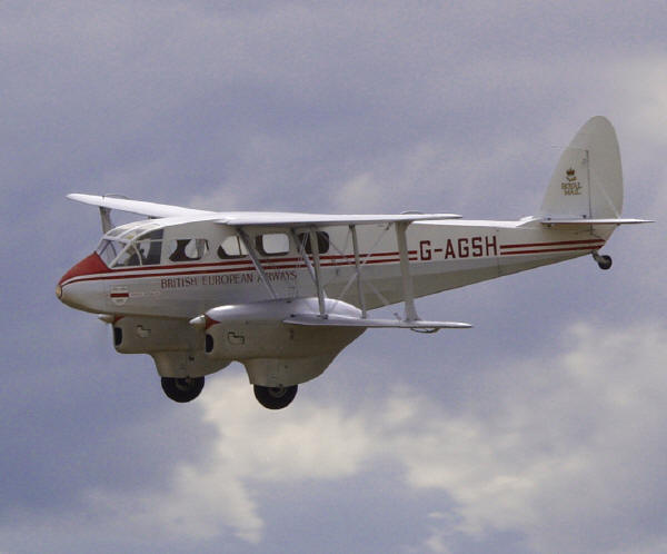
The De Havilland Dragon Rapide prototype was first flown on April 17th 1934 by H.S. Broad. Between 1934 and 1945 nearly 800 were built. By 1942 the annual production in Hatfield was 185. However, production space was needed for the Mosquito and so in 1943 production was transferred to the Brush Coachworks factory, near Loughborough. Between 1943 and 1945 340 aircraft were manufactured at this site.
G-AGSH, which Ted has modelled, was built at Brush coachworks for the RAF as a type Dominie in 1945. On the 25th of May the aircraft was classified as being surplus to requirements and was sold back to De Havilland for conversion to a civilian type Rapide. This aircraft is still flying today and has had more than 15000 flying hours.
Ted’s interest in the Dragon Rapide began whilst competing in F4C scale competitions. The Rapide was seen as having a good potential for a competitive, scratch built, twin-engined biplane that was not frequently modelled. A full-size aircraft was hangared at Carlisle Airport and the owner was extremely helpful. Access to the aircraft and the original maintenance and repair manual was provided. Everything that Ted wished for was included in the documentation; airframe details, rigging, incidence angles, even control throws. So a model to 17% scale and 8ft wingspan was built and was flown for five seasons between 1990 and 1994. Eventually, Ted’s thoughts turned to doubling the size to a 16ft model.
In March 1995 the decision was made to ‘go for it’ and what a magnificent job he did.
From a performance perspective, the key figures above are the wing and power loading. The figures given ensured there was sufficient power for a safe take-off and climb-out whilst the relative low wing loading would allow good recovery from the dramatic stall characteristics from the tapered wings.
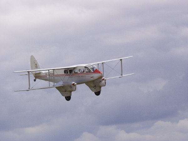

The airframe is structured upon a body strut, rigging wire and interplane strut arrangement. Many sketches were used to devise the body strut and rigging system to provide the strength required whilst being dismountable into handleable sized pieces. The model also had to be capable of construction in Ted’s workshop of limited facilities and space. The workshop is a double garage and also has to house a car; overspill indoors is not an option! The garage does have a loft space and this is the usual solution to storage difficulties. The requirements of subsequent transportation to the flying site were also considered at this early design stage.
To provide something better than an optimistic guess of the finished weight, wood and metal samples were weighed. This produced a basic unpainted weight estimate of 90lbs without ballast. An old textbook on airframe design published in the 1930’s was loaned to Ted by Mike Jackson and this included details of the basic strength and force calculations required.
The wing section used follows the full-size using a modified RAF 34 section with a 10% thickness/cord ratio, flat bottomed between the spars with a reflex trailing edge producing a washout effect along each aileron. Lower wing incidence is scale at +3.4 degrees whilst in an attempt to soften the stall the upper wing incidence was reduced form +3 to +2.5 degrees.
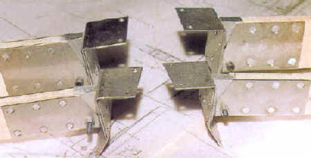
The wing construction began using foam cores. The wings have full depth spars and obechi veneer on the bottom and balsa leading edge sheeting with cap strips on top. The spars are a composite of 12mm birch ply to the inner strut with a 12mm doubler for the bolts. A Cyparis top and bottom inner strut to the tip with 0.8mm ply front forms a box section. Stainless steel plates (shown opposite) were riveted to both sides of each spar root for pin joint attachment of the wings to the fuselage.
The flying and landing wires hold the wings in a rigid configuration with inner and outer interplane struts. Wires are attached to steel plates bolted to the spars and designed to withstand +4G with a factor of safety of 3. In other words the elastic limit of the wires used was +12G. The wires are tensioned by turnbuckles with M4 threads. The wires themselves are steel tape 6mm x 0.8mm which are close to the scale size. The wires are in pairs to provide a further safety factor as the calculations were based on a single wire.
Fuselage construction closely follows the full-size with 1″ square spruce longerons reduced to 9mm square pine with diagonal spacers positioned according to the calculated stress distribution. 1/16″ ply sheeting was reduced to 0.8mm. The fuselage sides are internally braced with struts of 12mm birch ply with stainless steel fixings. External stringers are positioned over the ply sheeting, then fabric covered. A foam/glass cloth nosecone encloses the main servo batteries and 25W landing light. A spruce/ply framework glazed with 1mm polycarbonate sheet houses a 22″ tall ‘Pete’s Pilot’. The basic airframe is quite conventional, but the scale of the operation and the size of the structure gave significant problems in Ted’s workbench/cutting out area. The 8ft workbench still had the longerons overhanging by 2ft. Subsequent work had to be done standing on a chair!
The fuselage separates just forward of the fin/tailplane. Removal of only four bolts and one 9 way connector allows the complete assembly to be dismounted without disconnection of any linkages, control surfaces or rigging wires.
The tailplane incidence on the full size can be trimmed in flight by means of a screw jack operating on the tailplane leading edge. The model follows in principle allowing shims to be placed under the leading edge.
The undercarriage legs follow scale and include dual rate springs to absorb +3G landing loads per leg. There are 10″ wheels with pneumatic typres expertly built by Mike Jackson.
The engine nacelles bolt to the front and rear spars using steel brackets which also locate the undercarriage fixings fore and aft. The engines are bolted to a ply crutch which extends forwards from the wing spars and are clad in thin ply sheet where the outline shape is a single curvature and foam core glass cloth for the compound curves around the wheel fairings and cowling.
An acceptable level of workmanship was required for the safety and reliability of the model. This meant brushing up on old skills. Ted’s metalworking facilities only include a pillar driller and some basic hand tools; some help was necessary. A clubmate came to the to the rescue. Eddie Evans had a small Myford lathe and offered the facility and coaching to produce the turnbuckles. All of the sheet metalwork, riviting, drilling and slotting as well as forming lefthand and righthand threaded rods and tapped holes were down to Ted including brazing the steel tapes into the slot in each turnbuckle.
The control surfaces were hinged using commercially available items.
Elevators have no balancing in their construction or operation and so were been built as light as possible to minimise the static loads on each servo. Pushrod operation was chosen with a 14Kg-cm servo to each elevator half operating independently.
Ailerons used De Havilland geometry in order to retain the differential and static balance. Replicating this geometry required considerable effort to ensure appropriate accuracy. The aileron servos are installed in each lower wing and fitted to a characteristic looped horn which is 8″ long. The servo connects to the lower horn with a short 3mm diameter pushrod, ball-jointed at each end producing the required differential throw. Upper and lower ailerons are coupled with a pushrod operating within the hollow outer interplane strut. The weight of this rod and the cantilevered horns provides static balance. The gap between aileron leading edge and wing trailing edge is sealed with a fabric strip to improve aileron effectiveness. 13.5kg-cm servos were used.
The rudder is statically balanced with aerodynamic assistance following full size and operated with a duplex closed loop arrangement from a 14Kg-cm servo.
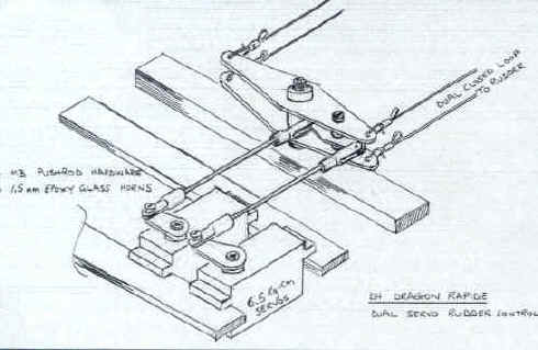
The rudder operation incorporates a dual servo system. The diagram opposite shows the design. The dual closed loop wire linkage is a scale feature and further provides redundancy. One locked-up servo will still enable a reduced throw to be controlled by the other. The bellcranks were fabricated from 1.5mm fibre board with metal clevises.
Operation of each pair of flaps (inboard and outboard of the engine nacelle) also follows the full-size with a piano type hinge along the full length of the hingeline and two pushrods spaced along each flap to prevent distortion and enable efficient operation directly in the propwash, even if deployed at excessive flying speed. A 11.5kg-cm servo in each nacelle drives each pair of flaps.

This critical stage of the project needed careful consideration. In particular, attention was paid to reduce the effect of possible faults that could develop.
All batteries and switches are duplicated to provide backup. Separate receiver batteries are used for improved isolation from interference. 6V batteries are used to ensure that the voltage drop, inevitable along 2m cable lengths to aileron and rudder/elevator servos, did not reduce the effectiveness of the servos.
A servo operated switch was installed to provide the facility to stop the engines.
An SM Services Large Model board was installed adjacent to the receivers. Opto- isolators on the board eliminate the feedback of noise to the receivers.
Two receivers were required with the controls spit between them so that either can control the aircraft to a large extent in the event of a component failure. Some thought was necessary on how to share the functions between the receivers. For example, the separation of rudder and throttles is not a good option since the loss of either would severely compromise the remaining control capability.
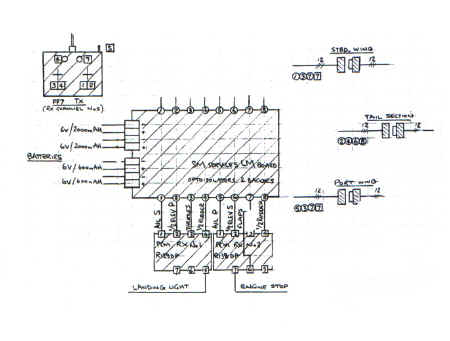
The final separation of the functions was decided as:
This provides the following in-case of a partial system failure:
If receiver 1 develops a fault then the second receiver allows the engines to be stopped in-case throttle control has also been lost. There will also be some, although reduced, aerodynamic control retained to all functions.
In this situation the throttles can still be controlled and there is still some aerodynamic control.
Note that in either case of receiver failure some rudder control is available. The system has also been designed such that the failure of any servo can be tolerated. The resulting design is a relatively safe and provides the pilot with some ability to control the aircraft in the event of a partial failure of the radio and control system.
The receiver aerials were extended to twice the supplied length and a capacitor used to prevent any disturbance to the RF section of the circuitry. The aerials exit the fuselage at each upper wing root at the trailing edge and are led to the tailplane with 1mm bore silicon sleeving. The ground range on testing the installation was greater than 250m using a FF7 transmitter and one section of the transmitter extended with both engines running at full throttle.
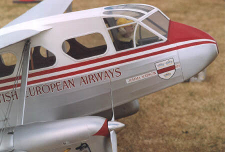
White primer was first applied. A bit of tidying-up was then necessary to add more thinned clear dope in some places, filler to the pinholes in the fibreglass skins and some further ironing down of the pinked edges of the rib tapes. A second coat resulted in an acceptable base for the finish coats. It took three coats of the white gloss to achieve a good colour depth and gloss finish. Two coats of silver were applied before painting the coach lines.
The BEA markings were initially going to be produced using film masks, but Ted was introduced to Eddie Ducker who had been a professional signwriter and he handpainted them straight on the model and where necessary applied gold leaf to produce a magnificent facsimile.
It takes approximately an hour to assemble the model.
Test flights commenced at Longhorsley in May 1999. These showed the expected characteristics:
Original engines runs produced a 6000 rpm difference on the engines. Various tuning attempts were made, but these affected the reliability of the engines. A telephone call to 3W agent suggested that a cover plate be fitted tothe inward facing carburettor of the port engine to counteract the ram effect from the propeller rotation adjacent to the fuselage wall. A couple of attempts at making plates later and the rpm was matched.
Using coordinated stick movements to turn, it has been an excellent model to fly.
As a postscript to this article it is sad to report that the model was crashed early in the 2002 season. The cause was a powered stall whilst in a turn. Even from a good height, Ted was unable to recover control.

Flying at Cosford 2001
For event tickets, merchandise and more visit our online shop.